16 Nov Speaker line supervision with NEO and ONE
In recent years, with the expansion of product and installation standards for emergency safety, like EN 60849:1998 and the current EN 50849:2017, as well as the standards for voice alarm systems in case of fire such as EN 54-16:2008 and TS 54-32:2015, public address and voice alarm systems include an integrity supervision of the speaker line.
When it comes to emergency systems, the system remains inactive until it is required to broadcast the essential voice alarm messages to preserve people’s lives. The system could not be used for long periods of time, so it is vital to know that it will be effective when needed. A critical part of these systems are the speakers and cable lines that connect them to the power amplifiers.
In a any fixed installation, like the evacuation system, these lines may suffer accidental alterations due to renovations in the site, either structural or decorative, as well as installation or maintenance works of other systems near the speakers and its lines.
The standard requirements determine that the supervision of the line integrity must be carried out in such a way that a fault in the speaker line caused by a short circuit, open circuit, or earth leakage is notified within 100 seconds.
In the speaker lines, the power signals (usually of constant voltage 70/100 V) are transmitted in the voice band (between 20 Hz and 20 KHz). The loudspeakers will respond to power signals within that frequency band, therefore the monitoring must not interrupt or modify these signals in order to avoid distortions in the messages to broadcast.
Speaker line supervision in LDA NEO and LDA ONE
LDA Audio Tech uses 3 methods complementary between them to guarantee the integrity of the speaker lines within their EN 54-16 certified systems, currently composed by NEO series and ONE series. The use of only one method or the combination of many of them will depend on the particularities of each speaker line:
| Impedance measurement | Filtered load (TFL-2) | End of line device (TFL-1) | |
| ✔ | ✔ | ✘ | |
 |
✔ | ✔ | ✔ |
Table 1: Speaker line supervision methods used by EN 54-16 certified systems from LDA Audio Tech
- Impedance measurement: Both ONE and NEO series include the speaker line impedance measurement functionality. It consists on the measurement of the real part of the complex impedance of all the line plus their speakers. Therefore, any failure that originates in any of these parts is detected. Since the speaker lines may be used while the measurement is done, a 19 KHz (non-audible) tone of calibrated amplitude is injected, allowing to measure both the voltage and electrical current of the speaker line. Therefore, it is possible to calculate the present impedance in the line and compare it with a previously set nominal impedance. This measurement has a default tolerance of 15 % and has an upper limit of 500 Ω @ 19 KHz for the detection of an open circuit. Both systems include an automatic calibration function to set the nominal impedance values.
Example: In a line of 83 Ω @ 19 KHz, the measurement will not be reliable if the deviation from the nominal impedance is lower than 13 Ω @19 KHz. In addition, if a speaker line has a load greater than 500 Ω @19 KHz, it will not be possible to detect if that line has an open circuit.
In order to avoid these limits, it is recommended to complement the impedance measurement method with the filtered charge method and/or the end of line device method.
- Filtered charge: This method is complementary to the impedance measurement method. It consists of introducing a frequency-selective resistive load into the line. It will only consume power in a very specific band of the signal that circulates on the line, which in the case of LDA is tuned to 19 KHz, in line with the measurement signal that is used in the impedance measurement method. This way, those lines with low speaker load can be compensated with this frequency-selective load.
Example: A line loaded with 550 Ω @19 KHz would be above the limit of open circuit detection using the impedance measurement method. When a filtered load in the 19 KHz frequency like the TFL-2 is connected, a load of 200 Ω will be added in parallel to the speaker line, resulting in an equivalent load of 146 Ω @ 19 KHz, which is within range of the impedance measurement method.
- End of Line Device: NEO series includes another functionality to complement the previous methods: the end of line device TFL-1. This device is a 19 KHz tone detector that, once installed at the end of the speaker line, will return a confirmation signal to the system. If the return signal is detected, the status of the line is correct, otherwise it will be indicated that there is a line fault. This method is recommended for those lines with complex impedances that cause fake faults and cannot be corrected by the previous methods.
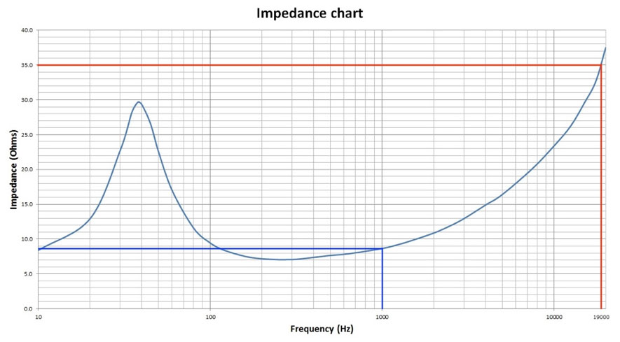
NOTE: All mentions about impedance values in this document are referred to the measurement frequency used in LDA systems (19 KHz). The nominal impedance of a loudspeaker is usually referred to 1 KHz and this may be widely different from its value at 19 KHz. Therefore, any theoretical calculation on the proper functioning of this method should consider the impedance frequency response of the loudspeaker.

Figure 1: Impedance frequency response of a loudspeaker. 8 Ω @ 1 KHz vs 36 Ω @19 KHz


